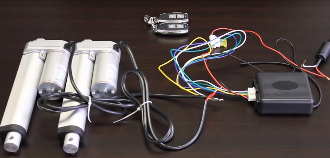
Electric linear actuators are commonly used in the industry to provide automated or controlled linear motion in an application. A large majority of electric linear actuators operate using a 12 VDC brushed DC motor, and can be controlled in many ways depending on how the unit is wired. First time users often want to know how to wire a linear actuator to rocker switches and control boxes, as these are commonly used control systems. In this article, we will take a look at wiring diagrams and their physical examples to better understand what is needed when wiring 12v linear actuators.

Wiring a 12V Actuator to a Rocker Switch

The simplest method of wiring a 12v linear actuator is to wire it with a rocker switch. Our wiring kit comes with multiple components that can help make the wiring process easier! This kit comprises of two wires (red and black colored), configured with jumpers to make connections more convenient. Other items included in the wiring kit are their Molex connectors, limit switches, diodes, and fuse holders containing fuses.
The installation kit can be used to limit the actuator stroke size and is also able to extend the length of the wires connected to the actuator. These two wires are important because they are used to provide a path for electricity to reach the linear actuator’s DC motor. There are two main types of rocker switches that can be chosen, a momentary or non-momentary type.
Momentary Rocker Switches
Momentary rocker switches aid in extending and retracting an actuator. Pressing and holding onto the switch in the UP position will extend the actuator. When pressing and holding onto the switch in the DOWN position, the actuator retracts. To stop the actuator’s movement, an operator would remove the pressure that was pressing onto the switch so that it can spring itself back into the shut off state.
Non-Momentary Rocker Switches
A non-momentary switch has three different positions. That is UP to extend, DOWN to retract and NEUTRAL to shut off power. Since non-momentary rocker switches have no internal spring, pressing the switch into position will leave it in that state until the operator presses it into another different position.
The simplest control system for a 12 VDC linear actuator for a user to implement will have to be a DPDT (double pole double throw) rocker switch. It can output DC current in both directions from the power supply, therefore it can control the linear actuator to extend and retract.

Wiring diagram of a rocker switch to an actuator
The linear actuator wiring diagram above can be achieved by following a few steps:
- The upper-left and lower-right terminals must be connected to the ground of the power supply.
- The upper-right and lower-left terminals must be connected to the +12V terminal of the power supply.
- The middle-right and middle-left terminals must be connected to the 2 inputs from the actuator.
This type of actuator switch wiring allows their operator to change the direction of electrical current flow entering the actuator in order to change travel direction. For a physical example of an actuator wiring circuit with a rocker switch, this video is a great example.

Physical wiring of a rocker switch to an actuator
Wiring with a Control Box

Depending on the application, many users would prefer to control their linear actuator with a control box that activates from wireless remotes. At Progressive Automations, we offer a large variety of control box options. They are mostly plug and play, so there is very little need for additional wiring.

Wiring diagram of a control box to an actuator
This wiring can be summarized into two simple steps.
- Connect the output of the control box to the input of the linear actuator.
- Connect the input of the control box to the output of the power supply.
For a physical example of an actuator wiring circuit with our control box, here’s a video for reference (the wiring starts at 1:05)!

Wiring with a Custom Control System
It is also possible to control our linear actuators with your own custom control system. Depending on the applications and control system requirements, the wiring diagram for the control system can be vastly different. However, the connection terminals for the linear actuator itself should remain consistent. The terminals one would need to find are the +12 VDC output terminal and the -12VDC output terminal. These should usually be labelled with +V and -V signs. No matter how complicated the custom control system is, the final output signal needs a 12 VDC current to drive the linear actuators. Look for any labels on the control unit or find them in the user manuals.
In Summary
There are many ways to wire a 12 VDC linear actuator, but the best method depends on your application and preferences. Wiring DPDT rocker switches to actuators works great if a wired control system was sufficient, however, we also have control boxes with wireless remotes for controlling actuators from a distance. If you have any further questions regarding how to wire a 12 VDC linear actuator, please do not hesitate in reaching out to us! We are experts in what we do and will be happy to help with any technical questions you have.

sales@progressiveautomations.com

1-800-676-6123


